Close Zoom
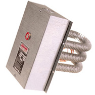
Vulcan Low-Temperature Duct Heaters are solidly-built comfort and air process heaters designed for use where the inlet air temperature does not exceed 100 °F (38 °C). They utilize a Finned Tubular Heater construction assembled to a rugged metal terminal housing with integral mounting flange for installation into the air duct. Over-temperature thermostats are included.
| 240 Volt 1 Ph | 480 Volt 3 Ph | Watts | Min. Duct Depth (in.) | Min. Duct Depth (mm) | Element Width (in.) | Element Width (mm) | Approx. Wt. (lb) | Approx. Wt. (kg) |
|---|---|---|---|---|---|---|---|---|
| VFT38-3B1 | VFT38-3C3 | 3000 | 8 | 203.2 | 6 | 152.4 | 10.1 | 4.4 |
| VFT312-5B1 | VFT312-5C3 | 5000 | 12 | 304.8 | 6 | 152.4 | 11.6 | 5.1 |
| VFT68-6B1 | VFT68-6C3 | 6000 | 8 | 203.2 | 12 | 304.8 | 14.1 | 6.1 |
| VFT318-7B1 | VFT318-7C3 | 7500 | 18 | 457.2 | 6 | 152.4 | 13.1 | 5.7 |
| VFT98-9B1 | VFT98-9C3 | 9000 | 8 | 203.2 | 18 | 457.2 | 19.7 | 8.6 |
| VFT612-10B1 | VFT612-10C3 | 10000 | 12 | 304.8 | 12 | 304.8 | 17.2 | 7.5 |
| VFT324-10B1 | VFT324-10C3 | 10000 | 24 | 609.6 | 6 | 152.4 | 14.6 | 6.4 |
| - | VFT128-12C3 | 12000 | 8 | 203.2 | 24 | 609.6 | 25.3 | 11 |
| - | VFT912-12C3 | 12000 | 12 | 304.8 | 18 | 457.2 | 24.3 | 10.6 |
| - | VFT158-15C3 | 15000 | 8 | 203.2 | 30 | 762 | 30.9 | 13.5 |
| - | VFT912-15C3 | 15000 | 12 | 304.8 | 18 | 457.2 | 24.3 | 10.6 |
| - | VFT618-15C3 | 15000 | 18 | 457.2 | 12 | 304.8 | 20.3 | 8.8 |
| - | VFT1212-16C3 | 16000 | 12 | 304.8 | 24 | 609.6 | 31.5 | 13.7 |
| - | VFT1212-20C3 | 20000 | 12 | 304.8 | 24 | 609.6 | 31.5 | 13.7 |
| - | VFT624-20C3 | 20000 | 24 | 609.6 | 12 | 304.8 | 23.4 | 10.2 |
| - | VFT918-22C3 | 22500 | 18 | 457.2 | 18 | 457.2 | 28.9 | 12.6 |
| - | VFT1512-25C3 | 25000 | 12 | 304.8 | 30 | 762 | 38.6 | 16.8 |
| - | VFT1218-25C3 | 25000 | 18 | 457.2 | 24 | 609.6 | 37.6 | 16.4 |
| - | VFT630-25C3 | 25000 | 30 | 762 | 12 | 304.8 | 26.4 | 11.5 |
| - | VFT1218-30C3 | 30000 | 18 | 457.2 | 24 | 609.6 | 37.6 | 16.4 |
| - | VFT924-30C3 | 30000 | 24 | 609.6 | 18 | 457.2 | 33.5 | 14.6 |
| - | VFT1518-37C3 | 37500 | 18 | 457.2 | 30 | 762 | 46.3 | 20.2 |
| - | VFT930-37C3 | 37500 | 30 | 762 | 18 | 457.2 | 38.2 | 16.6 |
| - | VFT1224-40C3 | 40000 | 24 | 609.6 | 24 | 609.6 | 43.8 | 19.1 |
| - | VFT1524-50C3 | 50000 | 24 | 609.6 | 30 | 762 | 54 | 23.5 |
| - | VFT1230-50C3 | 50000 | 30 | 762 | 24 | 609.6 | 50 | 21.8 |
| - | VFT1530-62C3 | 62500 | 30 | 762 | 30 | 762 | 61.7 | 26.9 |
| 240 Volt 1 Ph | 480 Volt 3 Ph | Watts | Min. Duct Depth (in.) | Min. Duct Depth (mm) | Element Width (in.) | Element Width (mm) | Approx. Wt. (lb) | Approx. Wt. (kg) |
|---|---|---|---|---|---|---|---|---|
| VFT38M-4B1 | VFT38M-4C3 | 4000 | 8 | 203.2 | 6 | 152.4 | 10.1 | 4.4 |
| VFT68M-8B1 | VFT68M-8C3 | 8000 | 8 | 203.2 | 12 | 304.8 | 14.1 | 6.1 |
| VFT318M-10B1 | VFT318M-10C3 | 10000 | 18 | 457.2 | 6 | 152.4 | 13.1 | 5.7 |
| - | VFT98M-12C3 | 12000 | 8 | 203.2 | 18 | 457.2 | 19.7 | 8.6 |
| - | VFT128M-16C3 | 16000 | 8 | 203.2 | 24 | 609.6 | 25.3 | 11 |
| - | VFT158M-20C3 | 20000 | 8 | 203.2 | 30 | 762 | 30.9 | 13.5 |
| - | VFT618M-20C3 | 20000 | 18 | 457.2 | 12 | 304.8 | 20.3 | 8.8 |
| - | VFT1218M-40C3 | 40000 | 18 | 457.2 | 24 | 609.6 | 37.6 | 16.4 |
| - | VFT924M-40C3 | 40000 | 24 | 609.6 | 18 | 457.2 | 33.5 | 14.6 |
| - | VFT1518M-50C3 | 50000 | 18 | 457.2 | 30 | 762 | 46.3 | 20.2 |
| - | VFT1524M-66C3 | 66700 | 24 | 609.6 | 30 | 762 | 54 | 23.5 |
| 240 Volt 1 Ph | 480 Volt 3 Ph | Watts | Min. Duct Depth (in.) | Min. Duct Depth (mm) | Element Width (in.) | Element Width (mm) | Approx. Wt. (lb) | Approx. Wt. (kg) |
|---|---|---|---|---|---|---|---|---|
| - | VFT318H-13C3 | 13250 | 18 | 457.2 | 6 | 152.4 | 13.1 | 5.7 |
| - | VFT324H-17C3 | 17750 | 24 | 609.6 | 6 | 152.4 | 14.6 | 6.4 |
| - | VFT330H-22C3 | 22000 | 30 | 762 | 6 | 152.4 | 16.1 | 7 |
| - | VFT618H-26C3 | 26500 | 18 | 457.2 | 12 | 304.8 | 20.3 | 8.8 |
| - | VFT624H-35C3 | 35500 | 24 | 609.6 | 12 | 304.8 | 23.4 | 10.2 |
| - | VFT918H-39C3 | 39750 | 18 | 457.2 | 18 | 457.2 | 29.9 | 13 |
| - | VFT630H-44C3 | 44000 | 30 | 762 | 12 | 304.8 | 26.4 | 11.5 |
| - | VFT1218H-53C3 | 53000 | 18 | 457.2 | 24 | 609.6 | 37.6 | 16.4 |
| - | VFT1518H-66C3 | 66300 | 18 | 457.2 | 30 | 762 | 46.3 | 20.2 |
| - | VFT930H-66C3 | 66000 | 30 | 762 | 18 | 457.2 | 38.2 | 16.6 |
| - | VFT1224H-71C3 | 71000 | 24 | 609.6 | 24 | 609.6 | 43.8 | 19.1 |
| - | VFT1230H-88C3 | 88000 | 30 | 762 | 24 | 609.6 | 50 | 21.8 |
| - | VFT1524H-88C3 | 88750 | 24 | 609.6 | 30 | 762 | 54 | 23.5 |
| - | VFT1530H-110C3 | 110000 | 30 | 762 | 30 | 762 | 61.7 | 26.9 |
| Construction Details: | |
| Heater Tubes: | Hairpin shape – steel sheath with steel fin full braze entire length |
| High temperature aluminum finish | |
| 3, 6, 9, 12, or 15 heater tubes depending on rating | |
| Element width equals end to end dimension across all elements | |
| Element outside hairpin dimension is approx. 4-3/4″ (120.7 mm) for all models | |
| Mounting: | Flanged lip includes 1/4″ (6.4 mm) predrilled holes spaced 4″ (101.6 mm) apart |
| Number of mounting holes varies with size | |
| Termination: | Screw and nut terminals pre-wired ready for power hook-up |
| Enclosure: | 16 gauge galvanized steel – general purpose – with wiring knockouts |
| Thermostats: | Overtemp manual and automatic thermostats provided |
| Require wiring through contactor | |
| Custom: | Custom lengths, watts, and volts are available |
| Option Code | Description |
| WX | Special Wattage |
| VX | Special Voltage |
| DX | Custom Duct Depths |
| SS | Stainless Sheath and Fins |
| GT | Gas Tight Element to Mounting Flange |
| EB4 | Moisture Resistant Terminal Housing |
| EB7 | Explosion Resistant Housing |
| HW | Heavy Wall “Armorwall Sheath |
| TC | Type J or K Thermocouple |
| BC | Bulb and Capillary Thermostat |
The best and easiest way to generate HTML tags for your website is using HTML cheatsheet.
1.0 Handling
1.1 Unpack and handle with care to avoid damage to heater and components
1.2 Make sure heater is protected from contamination during storage. A dry environment if preferred.
1.3 Refer to Application Data link for additional information related to heater system design and selection.
2.0 Safety
2.1 WARNING: Make sure power supply is turned off before installation or service of electric heater to prevent electrical shock or damage to equipment.
2.2 WARNING: Circuit should have separate disconnect means which shall be capable of being locked in the open position and also in sight from the heater.
2.3 WARNING: Wiring must conform to the National Electric Code and Local Regulations and should be performed by a qualified electrician. Make sure wiring is of a suitable temperature rating, amperage rating, and the location.
2.4 WARNING: When servicing, handle with caution, the heater surface may be hot.
2.5 WARNING: Do not install heater into a medium or an environment that could result in an explosion, fire, or hazardous condition. Contact Vulcan regarding heaters that are specifically designed for hazardous locations.
3.0 Installation and Operation
3.1 Caution: Make sure the heater supply voltage is the same as the rated heater voltage.
3.2 Caution: Heater should be properly grounded to prevent electrical shock hazard
3.3 Caution: Do not support or suspend heater from termination or wiring
3.4 A common cause of heater failure is contamination of the the internal heater components through the termination end of the heater. Make sure the heater is protected from contamination in the final application.
3.5 Make sure heater termination is not exposed to water or other liquids. Make sure that no dripping from condensation on cold water pipes or other sources can fall on any exposed electrical wiring connections or components.
3.6. Terminations should be properly tightened and connected to hook-up wiring. A loose connection will result in overheating at the connection and could lead to premature failure. Where possible, use a wrench or pliers to prevent twisting of the terminals during installation.
3.7 Duct heaters should be installed into the side or bottom of the duct to minimize heat transfer into the terminal enclosure. A mounting flange on each heater is predrilled for 3/16″ self tapping holes for installation into air duct.
3.8 Airflow direction is as noted on label attached to cover of unit.
Minimum air flow requirements are noted within catalog model section.
3.9 Make sure installation allows free air movement of air through the duct work and over the finned tubular heaters.
3.10 It is recommended that the heater be wired in such a way that a failure in the fan motor providing airflow will automatically shut off the heater.
3.11 The automatic over-temperature thermostat is set at 210 F and the manual reset limit thermostat set at 335 F 3.12 Heater should be wired per diagram supplied with unit or refer to our following website page for common circuits: Common_Wiring.pdf
3.13 Do not exceed 105% of rated voltage. Higher voltages result in higher wattage output which could damage the heater, system, or medium heated.
3.14 Thermostat notes:
3.14.1 Do not exceed amperage rating of thermostat. Wire through contactor(s) as required.
3.14.2 Thermostats are designed for heater control only and are not intended for use as a direct control of motors, fans, or other devices.
3.14.3 Do not use thermostat as a power disconnection means for the heater assembly.
4.0 Maintenance
4.1 For most applications, no heater maintenance is required.
4.2 Disconnect line switch prior to any testing or work on the heater 4.3 Check heater terminations after the initial 8 hours and tighten any loose terminal and jumper connections.
4.4 Recheck wiring periodically to ensure wiring has not become damaged, worn, or loose due to vibration or other application related conditions. Tighten, repair, or replace as needed.
5.0 Trouble Shooting
5.1 WARNING: Disconnect power supply to heater(s) before performing ny trouble shooting procedures.
5.2 Check supply voltage to heater to ensure there is power.
5.3 Check wiring circuit- make sure heater is properly wired and all supporting controls, relays, contactors, and other circuit related switches are also properly wired and functional.
5.4 Check heater(s)- No heat due to a heater failure is generally due to an open heater circuit. Check heater resistance across both terminals or leads. A reading of infinity (no continuity) indicates an open circuit within the element and the heater must be replaced.
5.5 Longer than normal heat up time for units with more than one heating element may be the result of an individual heating element failure.